 |
|
|
|
|
|
 |
||
| This is an example of how a simple fractal is generated. The fractal image will change every second; it can be "frozen" by moving the mouse pointer over it (moving the mouse out will resume the cycle). Clicking on the fractal will show all steps together. | ||
| These fractal images were constructed using a VRML viewer on Silicon Graphics machines, as an extra work I have done after an assignment for the Computer Graphics course given by Professor D. Thalmann, EPFL/LIG, in summer '98. The VRML code for each individual image, which contains the position, size and color for every single cube, was generated by a small C program. | ||
 |
A fractal is obtained by replacing certain elements of a fixed primary image according to a defined pattern with copies of that primary image, duely scaled, and repeating that operation over each copy until the desired depth is reached. |
| In order to generate a fractal, you need to define the following: | |
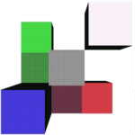
| The primary image that would serve as basic element for your fractal. In this example, this structure is simply a cube. | |
| Once you have chosen the basic element, you need to define the way in which your structure is going to be "split" when you increase the depth of your construction. In our case, the next step is generated by replacing each basic element (i.e. each cube) with an assembly of four identical cubes half its size placed in the same corner (that is, the position of the corner is the same for every element and for every depth; in our case, it is the bottom left-hand near corner of the basic cube). | |
| You can now repeat the "splitting" as many times as you wish. Each additional step you take to increase the depth of the fractal will improve the image and make it smoother and prettier. |
 |
In this example, the maximum depth plotted was 5, that is, the basic element was "split" 5 times according to the splitting rule as defined under (2) in the previous section. The reason why I stopped at 5 (as compared to 8 for example #1) was the enormous difference in the number of elements between two consecutive levels of depth. Indeed, this number is increased each time by 8, while in example #1 the increase rate is only 4. |
| In fact, I would have stopped at level 4 if I had been using SUN machines for rendering like in example #1; in this example however, I was working remotely on SUN machines, while the rendering was processed by Silicon Graphics terminals (the SGs are equipped with OpenGL routines at the hardware level, which makes the rendering of simple structures faster). | |
|
Computer Graphics Laboratory |